Showing posts with label buy aeduino due ebay. Show all posts

Monday, November 30, 2015

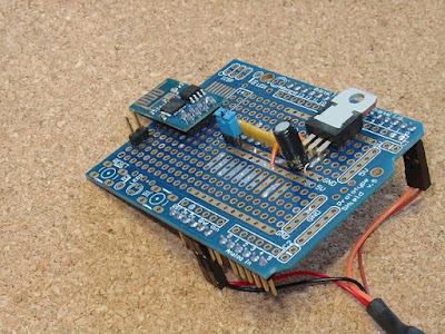
How to use ESP8266 WiFi Shield for Arduino and other micros-Robomart

This is a simple tutorial for how to use ESP8266 WIFI Shield for Arduino and other micros. This tutorial is very interesting. The step wise processor to use ESP8266 WiFi Shield for Arduino and other micros.


Step 1: Needed Parts
For this Project we will need some parts.This ESP8266-01 WiFi Shield needs the following parts, or similar. 
•36-pin header
Bourns 4606x-101-332LF Resistor Network
•1 off 1N5819 Schottky Diode 
•1 off 330R resistor 
Step 2: Structure


Step 3:Programming the WiFi Shield


// =============== start of pfodWifiWebConfig settings ==============

// update this define with the password from your QR code
//http://www.forward.com.au/pfod/secureChallengeResponse/keyGenerator/index.html
#define pfodWifiWebConfigPASSWORD "b0Ux9akSiwKkwCtcnjTnpWp"
You can also set your own configuration Access Point name, if you wish.
Step 4: How to Configur the WiFi Shield


Step 5: Using the WiFi Shield
In a complete project, you would mount a momentary push button on the outside of your project's box connected to the CONFIG_LINK, and instruct the user to press the push button and then power up the device to get into config mode. The code you loaded into the ESP8266-01 also drives the ESP8266's GPIO0 pin LOW when the module is in config mode, so you can connect a 270ohm resistor and LED between the 3.3V rail and GPIO0 and mount the LED on the outside of the box, to indicate to the user that they are in config mode.
As mentioned above any sketch you load into your Arduino, or other micro-processor, needs to a short delay to skip the debug output from the ESP8266 module. Other than that, to receive and send data via WiFi, from your sketch, you just read and write to your serial port (connected to D0,D1) at 9600 baud. So to ignore the ESP8266's debug output add to a short delay at top of the setup() method
void setup() {  
   delay(1000); // wait here for a second let ESP8266 complete powering up 
  // this also skips the WiFi Shield's debug output on power up
  // before starting the Serial connection.
  .... other setup code here
The example here uses an Arduino UNO but you can use any micro-processor, either 5V or 3.3V based that has a UART. If you use a 3.3V micro-processor, you will need to supply 5V to the WiFi Shield's power supply. This 5V will also be connected to the shield's 5V pin, so you need to check that this is acceptable for the micro you are plugging the shield into.


In the whole project , you CONFIG_LINK connected to your project a momentary push button mounted on the outside of the box , and press the push button and then the configuration mode to instruct the device to be powered .
Module Config mode when you load code also ESP8266 ESP8266-01 GPIO0 the drive pin is low , then you connect a 270ohm resistor and 3.3 GPIO0 between rail and led out of the box can mount LED , they indicate that the user is in config mode .
void setup() {  
   delay(1000); // wait here for a second let ESP8266 complete powering up 
  // this also skips the WiFi Shield's debug output on power up
  // before starting the Serial connection.
  .... other setup code here
The example uses an Arduino Uno , but any micro - processor can use , 5V or 3.3V that are based on either a UART . If you use a 3.3 micro - processor , WiFi Shield you will need to supply power to the 5V supply . This is acceptable for micro you are plugging into the hillside that needs to be examined , so it also 5V , 5V pin will be connected to the shield .
Then via WiFi from your Android mobile on and off in turn connect to the leadership of the United Nations .
That's it finished!!
Step 6: Conclusion
This Rev 2 of the ESP8266-01 WiFi Shield uses the cheap and readily available ESP8266-01 module. Other ESP8266 modules can also be used.
Once programmed you never need to program it again to set or change the network settings. They can all be set via a web page on a secure temporary WiFi network.
It is simple to interface to any micro that has a UART and works with on both 5V or 3.3V micro-processors.
No libraries are required to connect to this shield. It runs as a simple Serial to WiFi bridge.

You have completed this project sucessfully and easily. This is a simple tutorial. Feel free to edit this.
Have fun!!!

Thursday, November 26, 2015

Controlling of 8 LEDs by using Arduino UNO-Robomart

The step wise processor to control 8 LEDs using Arduino. This is a simple tutorial to control 8 LEDs using Arduino. This tutorial is very simple but more interesting. In this tutorial you set up LEDs to your breadboard.
 Step 1: What you will need


The parts are very simple for this easy project.
LEDs (3 red, 3 green and 2 blue)
Step 2: Put the LEDs and wires
In this step first of all you will need some parts which is mentioned in 2nd step after take the parts and LEDs you have to place the LEDs on the breadboard and you have reserved the positive  wire on the right side . After the wiring you will need to upload the code. The code is given below in 3rd step please upload this code and complete your project.
Step 3: Upload the code
//LED Pin Variables
int ledPins[] = {2,3,4,5,6,7,8,9}; //An array to hold the pin each LED is connected to
                                   //i.e. LED #0 is connected to pin 2, LED #1, 3 and so on
                                   //to address an array use ledPins[0] this would equal 2
                                   //and ledPins[7] would equal 9

/*
* setup() - this function runs once when you turn your Arduino on
* We the three control pins to outputs
*/
void setup()
{

  //Set each pin connected to an LED to output mode (pulling high (on) or low (off)
  for(int i = 0; i < 8; i++){         //this is a loop and will repeat eight times
      pinMode(ledPins[i],OUTPUT); //we use this to set each LED pin to output
  }                                   //the code this replaces is below


/*
* loop() - this function will start after setup finishes and then repeat
* we call a function called oneAfterAnother(). if you would like a different behaviour
* uncomment (delete the two slashes) one of the other lines
*/
void loop()                     // run over and over again
{
  oneAfterAnotherNoLoop();   //this will turn on each LED one by one then turn each off

}


void oneAfterAnotherNoLoop(){
  int delayTime = 100; //the time (in milliseconds) to pause between LEDs
                       //make smaller for quicker switching and larger for slower
  digitalWrite(ledPins[0], HIGH);  //Turns on LED #0 (connected to pin 2 )
  delay(delayTime);                //waits delayTime milliseconds
  digitalWrite(ledPins[1], HIGH);  //Turns on LED #1 (connected to pin 3 )
  delay(delayTime);                //waits delayTime milliseconds
  digitalWrite(ledPins[2], HIGH);  //Turns on LED #2 (connected to pin 4 )
  delay(delayTime);                //waits delayTime milliseconds
  digitalWrite(ledPins[3], HIGH);  //Turns on LED #3 (connected to pin 5 )
  delay(delayTime);                //waits delayTime milliseconds
  digitalWrite(ledPins[4], HIGH);  //Turns on LED #4 (connected to pin 6 )
  delay(delayTime);                //waits delayTime milliseconds
  digitalWrite(ledPins[5], HIGH);  //Turns on LED #5 (connected to pin 7 )
  delay(delayTime);                //waits delayTime milliseconds
  digitalWrite(ledPins[6], HIGH);  //Turns on LED #6 (connected to pin 8 )
  delay(delayTime);                //waits delayTime milliseconds
  digitalWrite(ledPins[7], HIGH);  //Turns on LED #7 (connected to pin 9 )
  delay(delayTime);                //waits delayTime milliseconds 

//Turns Each LED Off
  digitalWrite(ledPins[7], LOW);  //Turns on LED #0 (connected to pin 2 )
  delay(delayTime);                //waits delayTime milliseconds
  digitalWrite(ledPins[6], LOW);  //Turns on LED #1 (connected to pin 3 )
  delay(delayTime);                //waits delayTime milliseconds
  digitalWrite(ledPins[5], LOW);  //Turns on LED #2 (connected to pin 4 )
  delay(delayTime);                //waits delayTime milliseconds
  digitalWrite(ledPins[4], LOW);  //Turns on LED #3 (connected to pin 5 )
  delay(delayTime);                //waits delayTime milliseconds
  digitalWrite(ledPins[3], LOW);  //Turns on LED #4 (connected to pin 6 )
  delay(delayTime);                //waits delayTime milliseconds
  digitalWrite(ledPins[2], LOW);  //Turns on LED #5 (connected to pin 7 )
  delay(delayTime);                //waits delayTime milliseconds
  digitalWrite(ledPins[1], LOW);  //Turns on LED #6 (connected to pin 8 )
  delay(delayTime);                //waits delayTime milliseconds
  digitalWrite(ledPins[0], LOW);  //Turns on LED #7 (connected to pin 9 )
  delay(delayTime);                //waits delayTime milliseconds 
}


void oneAfterAnotherLoop(){
  int delayTime = 100; //the time (in milliseconds) to pause between LEDs
                       //make smaller for quicker switching and larger for slower

//Turn Each LED on one after another
  for(int i = 0; i <= 7; i++){
    digitalWrite(ledPins[i], HIGH);  //Turns on LED #i each time this runs i
    delay(delayTime);                //gets one added to it so this will repeat
  }                                  //8 times the first time i will = 0 the final
                                     //time i will equal 7;

//Turn Each LED off one after another
  for(int i = 7; i >= 0; i--){  //same as above but rather than starting at 0 and counting up
                                //we start at seven and count down
    digitalWrite(ledPins[i], LOW);  //Turns off LED #i each time this runs i
    delay(delayTime);                //gets one subtracted from it so this will repeat
  }                                  //8 times the first time i will = 7 the final
                                     //time it will equal 0
                                    
                                    
}

/*
* oneOnAtATime() - Will light one LED then the next turning off all the others
*/
void oneOnAtATime(){
  int delayTime = 100; //the time (in milliseconds) to pause between LEDs
                       //make smaller for quicker switching and larger for slower

  for(int i = 0; i <= 7; i++){
    int offLED = i - 1;  //Calculate which LED was turned on last time through
    if(i == 0) {         //for i = 1 to 7 this is i minus 1 (i.e. if i = 2 we will
      offLED = 7;        //turn on LED 2 and off LED 1)
    }                    //however if i = 0 we don't want to turn of led -1 (doesn't exist)
                         //instead we turn off LED 7, (looping around)
    digitalWrite(ledPins[i], HIGH);     //turn on LED #i
    digitalWrite(ledPins[offLED], LOW); //turn off the LED we turned on last time
    delay(delayTime);
  }
}

/*
* inAndOut() - This will turn on the two middle LEDs then the next two out
* making an in and out look
*/
void inAndOut(){
  int delayTime = 100; //the time (in milliseconds) to pause between LEDs
                       //make smaller for quicker switching and larger for slower

  //runs the LEDs out from the middle
  for(int i = 0; i <= 3; i++){
    int offLED = i - 1;  //Calculate which LED was turned on last time through
    if(i == 0) {         //for i = 1 to 7 this is i minus 1 (i.e. if i = 2 we will
      offLED = 3;        //turn on LED 2 and off LED 1)
    }                    //however if i = 0 we don't want to turn of led -1 (doesn't exist)
                         //instead we turn off LED 7, (looping around)
    int onLED1 = 3 - i;       //this is the first LED to go on ie. LED #3 when i = 0 and LED
                             //#0 when i = 3
    int onLED2 = 4 + i;       //this is the first LED to go on ie. LED #4 when i = 0 and LED
                             //#7 when i = 3
    int offLED1 = 3 - offLED; //turns off the LED we turned on last time
    int offLED2 = 4 + offLED; //turns off the LED we turned on last time
   
    digitalWrite(ledPins[onLED1], HIGH);
    digitalWrite(ledPins[onLED2], HIGH);   
    digitalWrite(ledPins[offLED1], LOW);   
    digitalWrite(ledPins[offLED2], LOW);       
    delay(delayTime);
  }

  //runs the LEDs into the middle
  for(int i = 3; i >= 0; i--){
    int offLED = i + 1;  //Calculate which LED was turned on last time through
    if(i == 3) {         //for i = 1 to 7 this is i minus 1 (i.e. if i = 2 we will
      offLED = 0;        //turn on LED 2 and off LED 1)
    }                    //however if i = 0 we don't want to turn of led -1 (doesn't exist)
                         //instead we turn off LED 7, (looping around)
    int onLED1 = 3 - i;       //this is the first LED to go on ie. LED #3 when i = 0 and LED
                             //#0 when i = 3
    int onLED2 = 4 + i;       //this is the first LED to go on ie. LED #4 when i = 0 and LED
                             //#7 when i = 3
    int offLED1 = 3 - offLED; //turns off the LED we turned on last time
    int offLED2 = 4 + offLED; //turns off the LED we turned on last time
   
    digitalWrite(ledPins[onLED1], HIGH);
    digitalWrite(ledPins[onLED2], HIGH);   
    digitalWrite(ledPins[offLED1], LOW);   
    digitalWrite(ledPins[offLED2], LOW);       
    delay(delayTime);
  }
}
After the wiring and uploading code you have successfully completed this project easily . If you find it attractive sufficient, you are free to edit it and use in your work. Feel free to comment and give suggestions in the comments section below.

Friday, November 20, 2015

How to make Arduino remotely controlled by Bluetooth or Bluetooth LE using phone - Robomart

Ever wanted to remotely control your Arduino ? Or read sensor values​​, or to make it something ? Maybe even create a remotely controlled robot ? Well now you can. The most basic example will cover; Switch off the LED on  and off .


Step -1: what you will need

  • 1 x 220 ohm (or similar) resistor
  • Assorted wire
  • 1 x smart phone (currently the app we will use only support
  • Android, but we are working on getting it accepted for iOS AppStore).
  • To use with a Bluetooth LE unit, the phone must support Bluetooth LE.
  • 1 x LED
  • 1 x Bluetooth or Bluetooth LE unit. The ones we have tested and works:
  • Bluetooth: HC-05 and HC-06 (will not be supported for iOS)
  • Bluetooth LE: HM-10

Step -2 : Hooking Everything Up 

Only now called BT ) Bluetooth or Bluetooth to connect the unit to :

Step-3: Code to the Arduino

5  ArduinoMobileIntegrationExamples/README.md
@@ -67,6 +67,11 @@ To run in app, copy the following files to the Internet:
An example that shows how a push button may be implemented in the app, and
state reported to an Arduino through a Bluetooth device.

+Two versions of Arduino code:
+* One using `PLabBTSerial.h` located in our `PLabBT` library.
+* One using only `SoftwareSerial.h` and a simple state machine to parse
+incomming text
+
To run in app, copy the following files to the Internet:
* `SimpleButtonExample.pde`


View
114  ...onExample/Arduino/SimpleButtonExampleSoftwareSerial/SimpleButtonExampleSoftwareSerial.ino
@@ -0,0 1,114 @@
/*
 * SimpleButtonExample SoftwareSerial
 *
 * Fjernstyr en LED på Arduine ved hjelp av SoftwareSerial og en tilstandsmaskin.
 *
 * Remotely controlled LED on Arduino using SoftwareSerial and a simple state machine.
 */
#include <SoftwareSerial.h>

// Enum definisjon. Brukt for å parse innkommende tekst
// Enum definition. Used to parse incomming text.
enum ReadState { INIT, O_ACCEPTED, F_ACCEPTED, END };

// State of parser
ReadState myState = INIT;

// Definer inn/utgangspinnene som brukes for send (TX) og motta (RX) for bluetooth
// Define I/O ports used for transmit (TX) and receive (RX)
const int BT_RX = 10;
const int BT_TX = 11;


// Hvilken utgang vi har lysene paa
// Which output we have the lights connected to
const int LIGHT_OUT = 4;


// Definer serieporten for kommunikasjon med bluetooth
// Define the serial port for communication with bluetooth
SoftwareSerial btSerial (BT_RX, BT_TX);

void setup() {
  // Start kommunikasjon med konsoll
  // Start communication throuhg console
  Serial.begin (9600);
  // Linja under trengs kun for Leonardo (kan slettes om du bruker Arduino UNO)
  // The following line is only needed for Leonardo (can be deleted if you are using Arduino UNO)
  while (!Serial);
  Serial.println ("Enkel knapp demonstrasjon med BLUETOOTH");
 
  // Setter utgangen for lyset
  // Set the output for our light
  pinMode (LIGHT_OUT, OUTPUT);
  digitalWrite (LIGHT_OUT, LOW);
 
  // Start kommunikasjonen med bluetooth enhet
  // Start communication with bluetooth unit
  btSerial.begin (9600);
}

void loop() {
  // Sjekker om vi har mottatt noe fra bluetooth enhet
  // See if anything has been received by Bluetooth unit
  if (btSerial.available()) {
    // Les mottatt bokstav
    // Read received character
    char recv = btSerial.read();

    // Gjør valg avhengig av tilstand
    // Do choises dependent on state
    switch (myState)
    {
      // INIT og END tilstand er egentlig like
      // INIT and END state are actually the same
      case INIT:  // Fallthrough
      case END:
        // Første bokstav vi aksepterer er kun en 'O'
        // First accepted is only an 'O'
        if (recv == 'O')
          myState = O_ACCEPTED;
        else
          myState = END;
        break;
      case O_ACCEPTED:
        // Andre bokstav kan enten være en ny 'O', en 'N' eller 'F'
        // Second character can either be an 'O', 'N' or 'F'
        switch(recv) {
          case 'O':
            myState = O_ACCEPTED;
            break;
          case 'N':
            myState = END;
            digitalWrite(LIGHT_OUT, HIGH);
            break;
          case 'F':
            myState = F_ACCEPTED;
            break;
          default:
            myState = END;
        }
        break;
      case F_ACCEPTED:
        // 'O' og 'F' er akseptable bokstaver
        // 'O' and 'F' are acceptable characters
        switch(recv) {
          case 'O':
            myState = O_ACCEPTED;
            break;
          case 'F':
            myState = END;
            digitalWrite(LIGHT_OUT, LOW);
            break;
          default:
            myState = END;
        }
        break;
    }
  }
  // Hvis vi har lyst til aa kunne skrive kommandoer i konsollvinduet, tar vi med dette
  // If we want to be able to write commands in the console window, we include this
  if (Serial.available () > 0) {
    btSerial.write (Serial.read ());
  }
}

When you have selected a version of the code.

  • Connect the Arduino to your computer.
  • Open the source file.
  • Press upload.

Step-4: Download the PLab app


Step-5: Running the sketch

First , sketch app can find it , a place where there should be . This means it must be uploaded to the Internet .
InterfacesInc.pde only need to upload the app so SimpleButtonExample.pde , internally covers
Sketch run , first connect the device to your Bluetooth or Bluetooth
  • Select the device from the list
  • Select wheter you want to connect to a Bluetooth or a Bluetooth LE device. To connect to a Bluetooth unit, this unit has to be paired with your phone. This is not neccessary when working with Bluetooth LE.
  • It is already uploaded here , it should be possible to directly use the upload . Be aware , and feeds into the app . This can be done by :
  • Leave settings andpainstakingly write the entire address into the "Sketch ID" field.
  • Go to settings and delete "URL address base" and "URL address end" 
If you have access to a web area , then use this to store your samples will be very easy to do .
After successfully loading the sketch , a white button should be visible on the brown background . Pressing the button to go dark a

Wednesday, November 18, 2015

How to make Motion Sensor Using Arduino - Robomart

In this tutorial you set up a motion sensor to your Arduino and a motion is detected or when to turn off the LED will give a simple example. With its new speed sensor wire and how to program the Arduino ? Well look no further. The principle is used in many fields of automatic door open , such as smart homes .... Arduino, HTML and CSS tutorial , keep the following .
Step 1: REQUIRED ELECTRONICS
 The parts required for this basic complex are

Step 2: HOW TO BUILDING THE  ELECTRONICS
  • If possible Place your controller on a breadboard! we are using Arduino micro so it is very convenient to put on a breadboard if we are not using a micro then we will need jumper wires to connect your Arduino to a breadboard so we can plug our output devices and sensors in more easily.
  • After all you are located , you can go ahead with the motion sensor and the ground should be labeled the pin Arduino you are going to place a wire from the ground.
  • You are going to take a pin on your Arduino and you let me use your PIN number five pins on the Arduino to a blank " out " label to connect the speed sensor are pin out.
  • Then you come out with the Arduino that is positive five volts to the VCC output speed sensors are going to connect the VCC output .
  • Next on my breadboard, LED is the positive side the lead now or go ahead and place both you and your leadership led to it being a small scar on the side of the one are the same for your breadboard Arduino place on the ground downside downside plug in, you then empty on the ground on a pin for making motion sensor LED pen to the ground can use a jumper wire to the positive Arduino LED Run a wire from the side.
  • I used this for a pin number 7 . We now proceed to the wires and controller programming , go to the next step .
Step 3: HOW TO CODING
int motion = 5;
int motionLed = 7;
void setup() {//ok i need to state what each pin will be doing. the led pin will//be an output and the motion pin will be an input.
pinMode(motion, INPUT);
pinMode(motionLed, OUTPUT);}
void loop(){ //what will happen in the sketch //if motion is detected we want to turn the led light on //if no motion is detected turn the led off //you also need to declare a variable to hold the sensor data long sensor = digitalRead(motion); //then the if statement to control the led
if(sensor == HIGH){
digitalWrite (motionLed, HIGH); }
else {
digitalWrite (motionLed, LOW); }
}