This is a simple tutorial for how to use ESP8266 WIFI Shield for Arduino and other micros. This tutorial is very interesting. The step wise processor to use ESP8266 WiFi Shield for Arduino and other micros.


Step 1: Needed Parts
For this Project we will need some parts.This ESP8266-01 WiFi Shield needs the following parts, or similar.
•1 off 0.1uF capacitor
•36-pin header
•Bourns 4606x-101-332LF Resistor Network
•1 off 1N5819 Schottky Diode
•1 off 330R resistor
•1 off 10uF capacitor
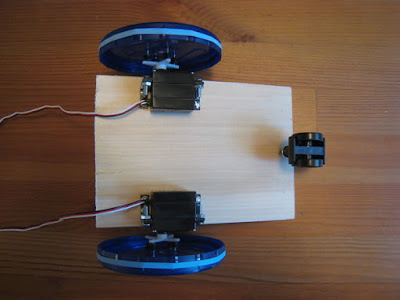
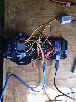
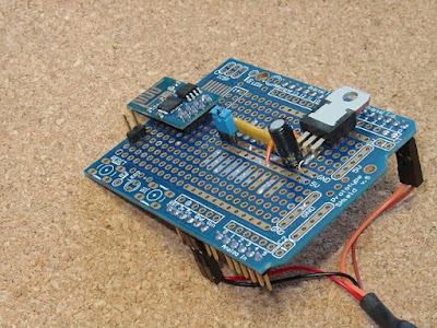
Step 2: Structure


Step 3:Programming the WiFi Shield


// =============== start of pfodWifiWebConfig settings ==============
// update this define with the password from your QR code
//http://www.forward.com.au/pfod/secureChallengeResponse/keyGenerator/index.html
#define pfodWifiWebConfigPASSWORD "b0Ux9akSiwKkwCtcnjTnpWp"
You can also set your own configuration Access Point name, if you wish.
Step 4: How to Configur the WiFi Shield


Step 5: Using the WiFi Shield
In a complete project, you would mount a momentary push button on the outside of your project's box connected to the CONFIG_LINK, and instruct the user to press the push button and then power up the device to get into config mode. The code you loaded into the ESP8266-01 also drives the ESP8266's GPIO0 pin LOW when the module is in config mode, so you can connect a 270ohm resistor and LED between the 3.3V rail and GPIO0 and mount the LED on the outside of the box, to indicate to the user that they are in config mode.
As mentioned above any sketch you load into your Arduino, or other micro-processor, needs to a short delay to skip the debug output from the ESP8266 module. Other than that, to receive and send data via WiFi, from your sketch, you just read and write to your serial port (connected to D0,D1) at 9600 baud. So to ignore the ESP8266's debug output add to a short delay at top of the setup() method
void setup() {
delay(1000); // wait here for a second let ESP8266 complete powering up
// this also skips the WiFi Shield's debug output on power up
// before starting the Serial connection.
.... other setup code here
The example here uses an Arduino UNO but you can use any micro-processor, either 5V or 3.3V based that has a UART. If you use a 3.3V micro-processor, you will need to supply 5V to the WiFi Shield's power supply. This 5V will also be connected to the shield's 5V pin, so you need to check that this is acceptable for the micro you are plugging the shield into.


In the whole project , you CONFIG_LINK connected to your project a momentary push button mounted on the outside of the box , and press the push button and then the configuration mode to instruct the device to be powered .
Module Config mode when you load code also ESP8266 ESP8266-01 GPIO0 the drive pin is low , then you connect a 270ohm resistor and 3.3 GPIO0 between rail and led out of the box can mount LED , they indicate that the user is in config mode .
void setup() {
delay(1000); // wait here for a second let ESP8266 complete powering up
// this also skips the WiFi Shield's debug output on power up
// before starting the Serial connection.
.... other setup code here
The example uses an Arduino Uno , but any micro - processor can use , 5V or 3.3V that are based on either a UART . If you use a 3.3 micro - processor , WiFi Shield you will need to supply power to the 5V supply . This is acceptable for micro you are plugging into the hillside that needs to be examined , so it also 5V , 5V pin will be connected to the shield .
Then via WiFi from your Android mobile on and off in turn connect to the leadership of the United Nations .
That's it finished!!
Step 6: Conclusion
This Rev 2 of the ESP8266-01 WiFi Shield uses the cheap and readily available ESP8266-01 module. Other ESP8266 modules can also be used.
Once programmed you never need to program it again to set or change the network settings. They can all be set via a web page on a secure temporary WiFi network.
It is simple to interface to any micro that has a UART and works with on both 5V or 3.3V micro-processors.
No libraries are required to connect to this shield. It runs as a simple Serial to WiFi bridge.
You have completed this project sucessfully and easily. This is a simple tutorial. Feel free to edit this.
Have fun!!!