This is a simple tutorial to make Arduino Mothbot. This is very interesting tutorial for this project. The step wise processer to make Arduino mothbot.


This project aims to design and using an Arduino Duemilanove microcontroller board is to build a simple light following robot. I really build a simple and cheaper robot project. I hope I have succeeded to make this project. It’s a simple tutorial to make Arduino Mothbot. To make this project you can follow this tutorial and copy the code.
Step 1:Needed Parts and Tools
•Safety Goggles
•Adjustable wrench or 11/32" hex wrench
•1/16", 5/32" and 7/32" drill bits
•Small Phillips (4-sided) screw driver
•Saw (optional)
Step 2:Planning Stage


In my planning phase I did not only looked at hardware and coding but did my electronics homework as well. I wanted to draw up a simple electronics schematic for this project so I could follow what was going on as I made it. You can see in the picture the different components, power lines, and the Arduino pins. Hopefully it's a clear diagram and also illustrate how simple the electronics for this project.
Step 3: Connecting Servos to Arduino


Below are the steps to connect the motor to the Arduino.
- Once the ground and power lines are identified connect the ground of the Arduino board to the ground strip on the solderless breadboard. Do not connect the power to the solderless breadboard yet.
- The first thing to do when setting up the solderless breadboard is to set up the ground (GND) and power (+6V) for the servos. I chose to use the two long strips on the board that would be closest to the Arduino.
- Attach the jumper wires to the end of the servo wires and then each servo to the solderless breadboard.
- Each servo has three wires that come out of them. Mine have a black, red, and white wire for each. The black is for ground, the red is for power, and the white is the control wire. Cut three jumper wires for each servo of the same size .
- Now use jumpers to connect the ground and power from each servo to the ground and power of the solderless breadboard.
- Now connect the control wires from each servo to the Arduino. Connect the left servo to digital output (PWM) 3 and the right servo to digital output (PWM) 11.
- Finally, connect the ground and power from the 4AA batteries to the solderless breadboard ground and power. Don't be alarmed if the servos start moving when your Arduino has no power or is not yet programed.
- Using the code you should now be able to run the motors in the forward, backward, left or right directions using the included functions.
/*
* Arduino Mothbot
*
* Digital Pin Wiring:
* pin 11 - Right Servo Signal
* pin 3 - Left Servo Signal
*
* License: This work is licenced under the Creative Commons
* Attribution-Share Alike 3.0 Unported License. To
* view a copy of this licence, visit
* http://creativecommons.org/licenses/by-sa/3.0/
* or send a letter to Creative Commons, 171 Second
* Street, Suite 300, San Francisco, California 94105,
* USA.
*/
//------------------------------------------------------------------------
// START OF ARDUINO MOTHBOT SETUP
//--- Library
#include <Servo.h>
//--- Pin Definitions
#define LEFTSERVOPIN 3 //The digital pin that the left servo is connected to
#define RIGHTSERVOPIN 11 //The digital pin that the right servo is connected to
//--- Servo Setup
Servo leftServo;
Servo rightServo;
//--- Speed Setup
int robotSpeed = 75; //set the speed of the robot
int rightSpeed = 50;
int leftSpeed = 50;
//--- Delay Threshold
int delayParam = 10; //Supported Times - 0 - 255 (0 to 25.5 Seconds) value * 100 milliseconds
// END OF ARDUINO MOTHBOT SETUP
//------------------------------------------------------------------------
//------------------------------------------------------------------------
//START OF ARDUINO MOTHBOT PROGRAM
//--- The program setup
void setup()
{
Serial.begin(9600); //Starts the serial port
robotSetup(); //sets the state of all neccesary
//pins and adds servos to your sketch
}
//--- The main program code
void loop()
{
Serial.println("Forward");
goForward();
delay(delayParam * 100);
goStop();
}
//END OF ARDUINO MOTHBOT PROGRAM
//------------------------------------------------------------------------
//------------------------------------------------------------------------
//START OF ARDUINO MOTHBOT FUNCTIONS
//--- The setup for the robot
void robotSetup()
{
//--- Set the speed of the robot
setSpeed(robotSpeed);
//--- Set up the servos
pinMode(LEFTSERVOPIN, OUTPUT); //sets the left servo signal pin
//to output
pinMode(RIGHTSERVOPIN, OUTPUT); //sets the right servo signal pin
//to output
leftServo.attach(LEFTSERVOPIN); //attaches left servo
rightServo.attach(RIGHTSERVOPIN); //attaches right servo
//--- Tell the robot to stop the servos
goStop();
}
//--- Set the speed of the robot between 0-(stopped) and 100-(full speed)
void setSpeed(int newSpeed)
{
setSpeedLeft(newSpeed); //sets left speed
setSpeedRight(newSpeed); //sets right speed
}
//--- Set the speed of the left wheel
void setSpeedLeft(int newSpeed)
{
if(newSpeed >= 100) {newSpeed = 100;} //if speed is greater than 100
//make it 100
if(newSpeed <= 0) {newSpeed = 0;} //if speed is less than 0 make
//it 0
leftSpeed = newSpeed * 0.9; //between 0 and 90
}
//--- Set the speed of the right wheel
void setSpeedRight(int newSpeed)
{
if(newSpeed >= 100) {newSpeed = 100;} //if speed is greater than 100
//make it 100
if(newSpeed <= 0) {newSpeed = 0;} //if speed is less than 0 make
//it 0
rightSpeed = newSpeed * 0.9; //scales the speed to be
}
//--- Move the robot forward
void goForward()
{
leftServo.write(90 + leftSpeed);
rightServo.write(90 - rightSpeed);
}
//--- Move the robot backward
void goBackward()
{
leftServo.write(90 - leftSpeed);
rightServo.write(90 + rightSpeed);
}
//--- Move the robot right
void goRight()
{
leftServo.write(90 + leftSpeed);
rightServo.write(90 + rightSpeed);
}
//--- Move the robot left
void goLeft()
{
leftServo.write(90 - leftSpeed);
rightServo.write(90 - rightSpeed);
}
//--- Stop the robot
void goStop()
{
leftServo.write(90);
rightServo.write(90);
}
//END OF ARDUINO MOTHBOT FUNCTIONS
//------------------------------------------------------------------------
Step 5: Integrating the On/Off switch


Step 6: How to Integrate the Light Sensors


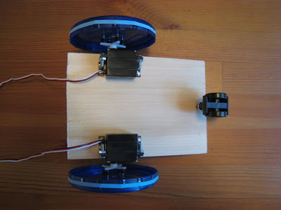
Step 7: Make the Mothbot Body
The robot you're building is really no good unless it can hold itself together. For this reason it needs a body. I tried my best to make this as simple a construction project as possible. You are, however, going to have to do a little work on your own to figure out the right measurements. I suggest the age old "measure twice, cut once" method.
Step 8: How to make the wheels
Wheels, It was a difficult problem for me. I actually certified robot wheels but they were realized a very heavy. I have chosen to servos there was no way to attach them . I have a similar project for the high school remembered that when using the jar lids . So it's a great looking robot wheel option was off to the store .
A wheel of a Ziploc Twist ' n Loc lid of the container is made from . Other good peanut butter jar lids or other food items are on . I advocate wasting food but save your eyelids and you can get the right size for your robot project is not . I thought I have collected leftover containers used to hold parts .
Step 9: Complete the Arduino Mothbot
With the body and wheels assembled it's easy to place the Arduino and solderless breadboard just a top the robot body. Make sure you can still reach the USB input on the Arduino in case you need to change the programming. I used some black electrical tape underneath each to stick them to the body. Electrical tape is easy to remove and holds quite well.
- Tape the Arduino and solderless breadboard to the top of the robot body that you've built.
- Using tape again it's a good idea to connect the 4AA battery holder and the 9V battery to the body. Make sure the wires reach.
- Connect the servo wires to the solderless breadboard if you had removed them previously.
- Connect the Arduino power
- Connect the servo motor power
- Now place your robot on the ground and press the on/off switch! It should now come to life and chase the light around the room.
As a future add-on project I would include a simple bumper or wall sensor. This would be a switch, much like the On/Off button used in this project. However, when the button was pushed it would tell the robot to reverse direction, turn left or right, and continue with the program. Once that is completed this robot would be a great little testing platform for other sensors and devices.
You have done this project sucessfuuly. Have Fun!!!
No comments:
Post a Comment